Actuators
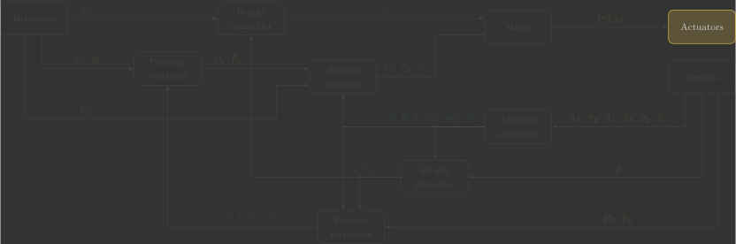
In this section, you will implement the actuators() function, which receives the \({\color{var(--c3)}\text{PWM}}\) commands and sends them to the BLDC motor drivers.
Overview
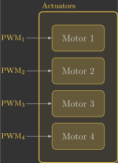
The following diagram illustrates the internal structure of the actuators function:
Before we begin, it is important to understand a few concepts:
- Arming the quadcopter means enabling the motors to operate. This is done manually through the Crazyflie Client and can be checked in the firmware using the
supervisorIsArmed()function. - The motors are controlled using the
motorsSetRatio(id, ratio)function, whereidspecifies the motor andratiospecifies its power level:- The Crazyflie has four motors, identified as
MOTOR_M1,MOTOR_M2,MOTOR_M3, andMOTOR_M4. - The power level ranges from
0(off) toUINT16_MAX(maximum power).
- The Crazyflie has four motors, identified as
- The
motorsStop()function turns off all four motors at once.
Implementation
The first step in your function is to check whether the quadcopter is armed. If it is not, all motors must be turned off.
If the quadcopter is armed, we perform a second check: whether the height reference \(z_r\) is greater than zero. In other words, we check if the quadcopter has been instructed to take off.
If the height reference is greater than zero, the PWM values stored in the global variables are applied to each of the four motors. Otherwise, all four motors are commanded to a fixed PWM value of 10%.
This constant 10% duty cycle is known as the idle PWM. It keeps the BLDC motors spinning at a low speed so they are already running when takeoff is commanded, allowing them to respond immediately and reliably.
The code below implements this logic.
62 63 64 65 66 67 68 69 70 71 72 73 74 75 76 77 78 79 80 81 82 83 84 85 86 87 88 89 90 91 | |
You can simply copy and paste the code above. However, take some time to understand what each line does (the comments are there to guide you).