Mixer
In this section, you will implement the mixer() function, which converts the total thrust and torques generated by the propellers \({\color{var(--c2)}f_t}\), \({\color{var(--c2)}\tau_x}\), \({\color{var(--c2)}\tau_y}\), and \({\color{var(--c2)}\tau_z}\), into the corresponding motor \({\color{var(--c3)}\text{PWM}}\) commands.
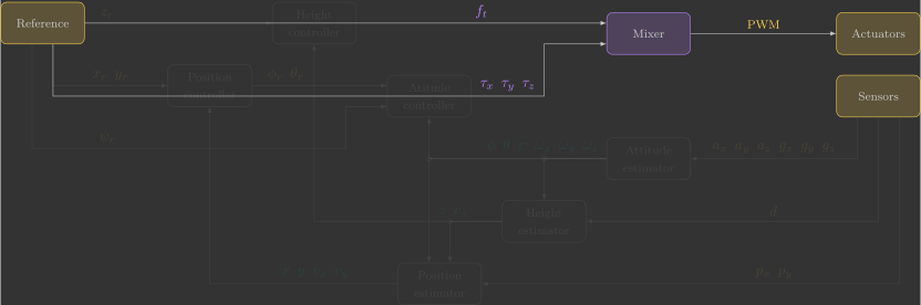
Overview
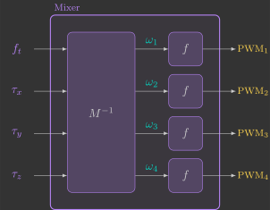
Previously, we derived the inverse mixer matrix \(M^{-1}\), which converts total thrust and torques generated by the propellers \({\color{var(--c2)}f_t}\), \({\color{var(--c2)}\tau_x}\), \({\color{var(--c2)}\tau_y}\), and \({\color{var(--c2)}\tau_z}\) into the squared angular velocities of the four motors, \({\color{var(--c1)}\omega_1}\), \({\color{var(--c1)}\omega_2}\), \({\color{var(--c1)}\omega_3}\), and \({\color{var(--c1)}\omega_4}\):
We also identified the motor coefficients \(a_2\) and \(a_1\), which convert the motor angular velocity \({\color{var(--c1)}\omega}\) into the corresponding \({\color{var(--c3)}\text{PWM}}\) command:
Combining these two relationships gives us the complete mixer logic:
Implementation
Implement this logic in the mixer function(1):
- Declare the previously identified quadcopter parameters as local constants.
77 78 79 80 81 82 83 84 85 86 87 88 89 90 91 92 93 94 95 96 97 98 99 100 101 102 103 | |
Warning
Be careful when taking the square root of negative numbers. Check whether each value of \({\color{var(--c1)}\omega}^2\) is non-negative before computing its square root.
Validation
To validate your implementation, perform a few simple tests by verifying that the correct motors increase or decrease their angular velocities.
Warning
Since the estimators and controllers have not been implemented yet, we must temporarily modify a few functions (essentially creating a bypass) in order to test the mixer.
Because the quadcopter is not being controlled, comment out the lines that check whether the altitude reference \({\color{var(--c3)}z_r}\) is greater than zero:
62 63 64 65 66 67 68 69 70 71 72 73 74 75 76 77 78 79 80 81 82 83 84 85 86 87 88 89 90 91 | |
We will use the variables transmitted by the Crazyflie Client's Command-Based Flight Control interface to command the total thrust \({\color{var(--c2)}f_t}\) in increments of \(0.01~\text{N}\)(1), and the roll torque \({\color{var(--c2)}\tau_x}\)(2) and pitch torque \({\color{var(--c2)}\tau_y}\) in increments of \(0.001~\text{N}\cdot\text{m}\). Modify the code as follows:
-
We first multiply by \(2\), then round the result, and finally divide by \(100\) (or \(1000\)). This ensures rounding to two (or three) decimal places.
-
The roll torque \({\color{var(--c2)}\tau_x}\) requires a sign inversion because the \({\color{var(--c1)}y}\) axis, controlled by the ← and → buttons, is opposite to the positive roll torque direction.
72 73 74 75 76 77 78 79 80 81 82 83 84 85 86 87 88 89 90 91 92 93 | |
Thrust
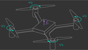
Arm the quadcopter and vary the thrust command \({\color{var(--c2)}f_t}\) using the Up and Down buttons. Verify that all four motors increase and decrease their angular velocities accordingly.
Roll torque
Arm the quadcopter and vary the roll torque \({\color{var(--c2)}\tau_x}\) using the ← and → buttons. Verify that only right motors \({\color{var(--c1)}3}\) and \({\color{var(--c1)}4}\) speed up for positive values, while left motors \({\color{var(--c1)}1}\) and \({\color{var(--c1)}2}\) speed up for negative values.
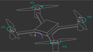
Pitch torque
Arm the quadcopter and vary the pitch torque \({\color{var(--c2)}\tau_y}\) using the ↑ and ↓ buttons. Verify that only back motors \({\color{var(--c1)}2}\) and \({\color{var(--c1)}3}\) speed up for positive values, while front motors \({\color{var(--c1)}1}\) and \({\color{var(--c1)}4}\) speed up for negative values.
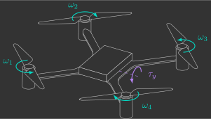
Yaw torque
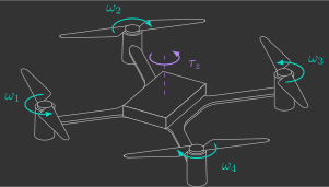
Arm the quadcopter and vary the yaw torque \({\color{var(--c2)}\tau_z}\) using the ← and → buttons(1). Verify that only clockwise motors \({\color{var(--c1)}2}\) and \({\color{var(--c1)}4}\) speed up for positive values, while counter-clockwise motors \({\color{var(--c1)}1}\) and \({\color{var(--c1)}3}\) speed up for negative values.
- Modify the reference function so that the ← and → buttons adjust the yaw torque \(\tau_z\) in increments of \(0.0001\,N\cdot m\). Notice that this uses one additional decimal place.